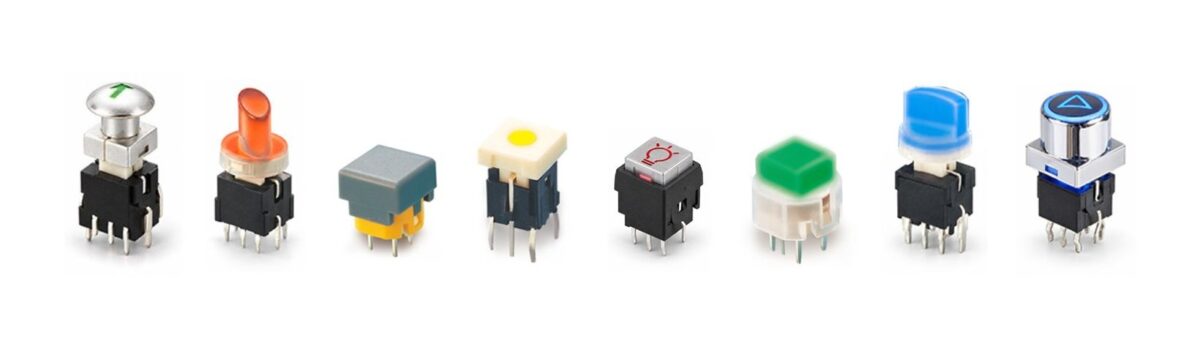
We know that trying to read a data sheet can feel like you’re being overwhelmed with information and technical jargon, so in this article we’re breaking down the individual parts of a PCB push button data sheet.
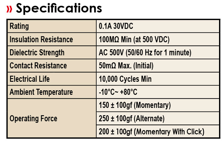
Switch Specifications
The specification table covers the technical ratings and information that you need to know in order to select the correct switches for your application, so that they function well and don’t get damaged.
- Rating – the maximum electrical current it can safely carry (Amperage) and the maximum continuous voltage it can withstand (Volts Direct Current).
- Insulation Resistance – how well an insulator can prevent current flowing between two conductors or flowing to ground; measured in megohms (MΩ).
- Dielectric Strength – measures the strength of an insulator by testing the maximum voltage it can withstand before breaking down.
- Contact Resistance – the amount of resistance to the flow of electricity between two contacts; measured in megohms (MΩ).
- Electrical Life – how many electrical cycles the switch can withstand before it may start to deteriorate.
- Ambient Temperature – the environmental temperature range that the switch can be used in. Temperatures outside of this range can cause damage.
- Operating Force – the force required to press down and actuate the switch; measured in gram-force (gf).
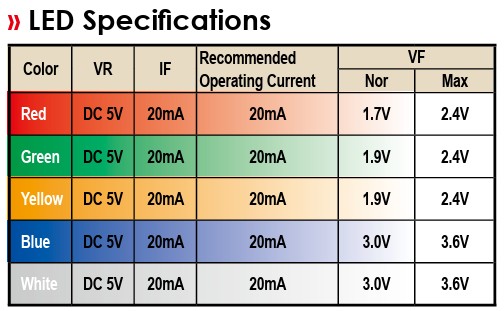
LED Specifications
The LED specifications of a switch let you know the current and voltage of the LED element itself, so that you don’t unintentionally overpower or damage it when installing and using the switch.
- Reverse Voltage (VR) – the max voltage that an LED can withstand with current flowing in the reverse (i.e. wrong) direction.
- Forward Voltage (VF) – the minimum voltage required to make the LED illuminate. It is important to note the VF, as different LED colours are determined by different semiconductor materials, which have varying conductivity. So the voltage needed to power a red LED is far lower than what is needed for a blue LED, for example.
- Forward Current (IF) – measured in milliamperes (mA), it is the electrical current that flows through an LED and directly controls its brightness. Too high of a current creates a brighter light but can also shorten the LEDs lifespan greatly.
- Recommended Operating Current – in relation to the IF measurement, the recommended operating current advises the best milliamperage for bright illumination that doesn’t overpower the component.
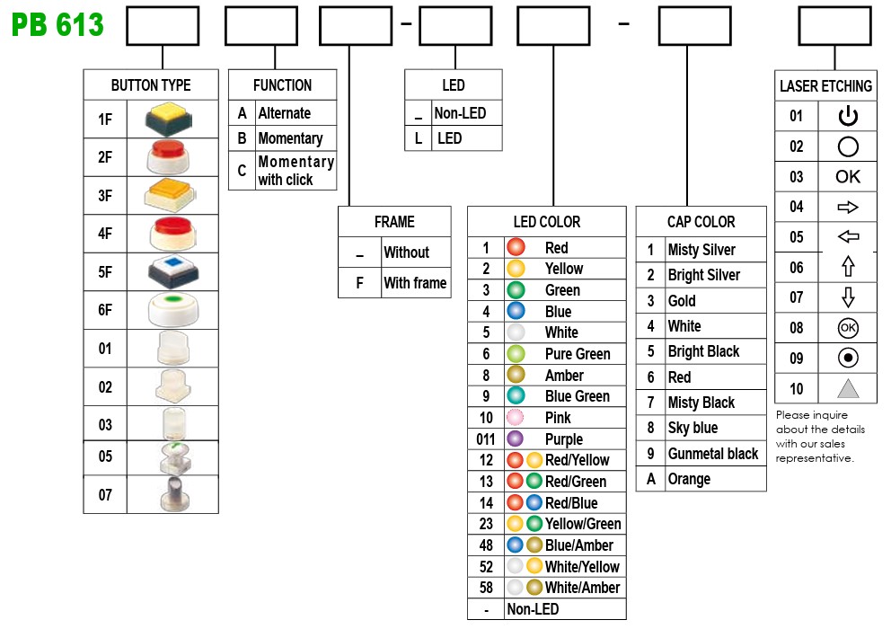
Selector Guide
The selector guide allows you to select the elements of the switch such as the cap style, LED colour and function, so that you can order components with an exact part number.
- Button Type – this refers to the shapes and sizes of caps that you can choose from when ordering these switches.
- Function – many PCB push buttons are available with a momentary or latching (alternate) function, as well as the option for ‘momentary with click’, which is a tactile-style configuration that features an audible clicking sound when pressed.
- Frame – adding a frame to push button switches can provide extra stability for the actuator, but they can also be selected as an aesthetic preference.
- Laser Etching – when ordering these switches, you can choose from a range of symbols to be laser etched onto the switch caps. These can either be clear to show LED illumination, or non-illuminated and coloured.
Example Part Number
PB61305BL-3-106
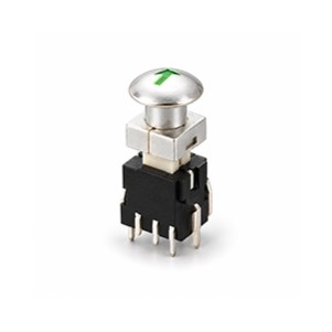
This PB613 push button switch features a mushroom style cap (05), a momentary function (B), and LED illumination (L). It has a green LED (3), a misty silver cap (1) and laser etching of an upwards pointing arrow (06).
Circuit Information
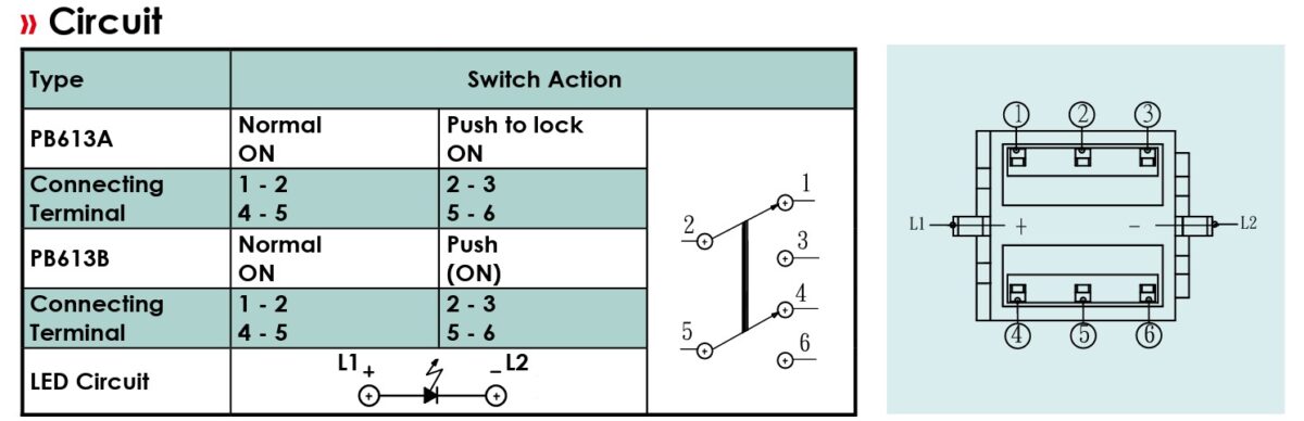
The table on the left breaks down which terminals connect to each other to actuate the circuit. In this example, 2 and 5 connect to 1 and 4 when the switch is in its normal position. When the switch is pressed, the contacts move so that 2 and 5 connect to 3 and 6, which connects the circuit (DPST) or changes the route of the current (DPDT).
The diagram on the right indicates where the pins for each of the connecting terminals are located on the bottom of the switch.
‘L1’ and ‘L2’ represent the pins that control the LED if the switch is illuminated. For an LED to light, it must have one positive pin (+) and one negative pin (- ), or multiple pins if it is RGB. For bi-colour illumination, the polarity between L1 and L2 is reversed when the button is pressed.
Operating Characteristics
The final section of the data sheet contains photos and drawings of each of the cap styles – and their related part numbers – to give a better idea of the available options.
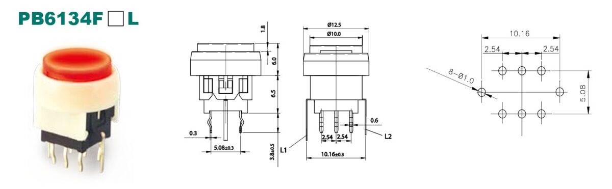
A photo of the switch and cap 4F, which has a round actuator, full illumination and a frame.
A switch drawing lets you know the precise measurements of the pins, body and actuator, so that you can make sure it is a suitable size for your project.
This PCB layout diagram shows the distances between the pins, so mounting holes can be accurately placed.
Hopefully this breakdown of our PCB push button data sheets will make ordering your next switches that bit simpler. But if you still have questions or want to know more about how to order, our experienced and friendly Sales Engineers are always on hand to help!
Interested in our products? Speak to us today!
How to place an order?
We operate Monday – Thursday (8 am – 5 pm) and Fridays (8 am – 4.30 pm)
Call us on +44 (0) 1234 213600 to speak to our Sales Engineers or e-mail us
on sales@rjselectronics.com alternatively, leave us a message using our online contact form.
View our full product range here | Download our recent product catalogue
Switch on.
Sign up to our mailing list for the latest news, product notification and so much more!
Just one click away…